- Connectors
Evolution of FPC/FFC Connectors


Do you know the various types of FPC/FFC mating methods, mounting styles, and flexible cable shapes? Keep reading below to discover them all!
Click Here to Learn About "The History of Kyocera's FPC/FFC Connectors".
Various Mating Methods of FPC/FFC
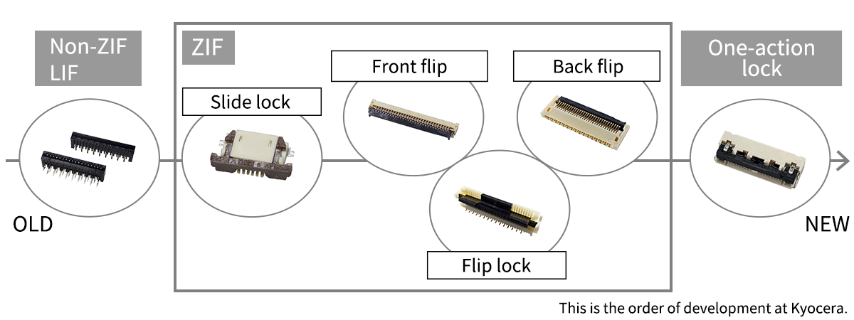
From the past to the present, improvements have been made to the lock structure, and various mating methods have been developed. For example, the Non-ZIF type, which is easier and less costly to operate, the ZIF type, which requires no force during insertion, and the one-action locking type, which requires only one operation (one action) to complete locking, have been developed recently.
Clicking on each name will take you to its product search page.
- Non-ZIF:Property of connectors that do not have a ZIF structure. FPC/FFCs are inserted directly into this type of connector, relying on contact friction to retain the FPC/FFC.
- LIF: Abbreviation of Low Insertion Force. A contact structure designed to suppress the mating force, while allowing enough force to retain an FFC/FPC.
- ZIF:Abbreviation of Zero Insertion Force. When inserting or removing an FFC or similar to/from a ZIF connector, the actuator reduces insertion/removal. All Non-ZIF type connectors do not have this structure.
- Slide lock:This type of connector is unlocked by sliding the slider to insert and remove the FPC/FFC.
- Front flip:This type of connector has an actuator located on the FPC/FFC insertion side.
- Flip lock:This type of connector allows the FPC/FFC to be inserted and removed by “flipping” the actuator.
- Back flip:This type of connector has an actuator located behind the FPC/FFC insertion port.
- One-action lock:This type of connector enables the FPC/FFC to be locked in a single operation (one action) of inserting the FPC/FFC. A typical ZIF-type FPC/FFC connector requires three operations (three actions): (1) opening the lock, (2) inserting the FPC/FFC, and (3) closing the lock.
Change of Mounting Method
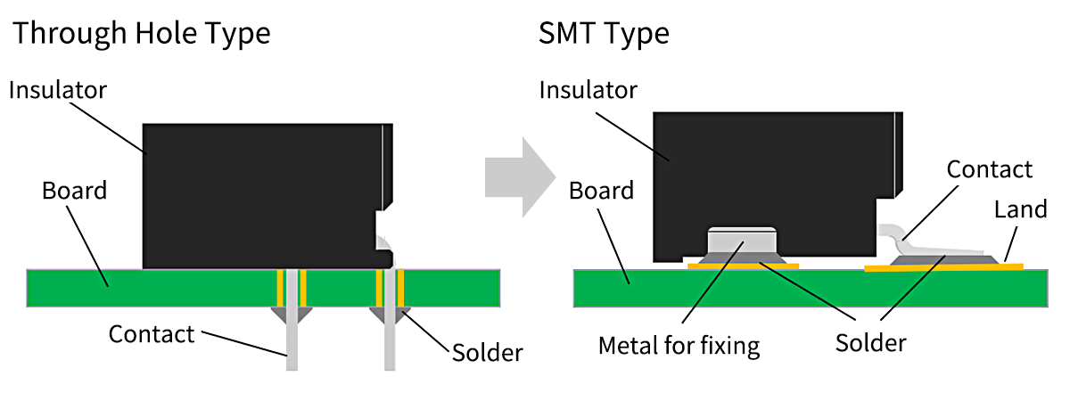
SMT Type has become mainstream instead of Through Hole Type
Keywords The Official Mascot of Kyocera’s Electronic Components Division: Eletan
Click here to learn more about Eletan
What is Through Hole Type?
A method of mounting components by inserting their soldered terminals into holes drilled in the board.
Features
- Terminals penetrate holes in the board, making them resistant to external forces.
- Difficult to miniaturize and high-density mounting.
- Occupies both sides of the boards.
What is SMT Type?
Abbreviation of Surface Mount Technology.
A method of producing electronic circuits on a printed circuit board (PCB) by applying solder paste and placing components on the PCB's surface before the solder is melted in a reflow oven.
Features
- Surface-mounted, so the external force is weaker than Through Hole Type (Fixing metal is required).
- Smaller size and high-density mounting are possible.
- Mounting is only on the surface of the board, and the back side can also be used.
Downsizing
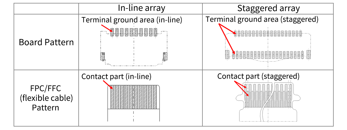
As the pitch became smaller from 1.25 mm to 0.2 mm, the array of right-angle types changed from an in-line array to a staggered array.
Pitch | ||||||
|---|---|---|---|---|---|---|
1.25mm | 1.0mm | 0.8mm | 0.5mm | 0.4mm | 0.3mm | 0.2mm |
In-line array | Staggered array | |||||
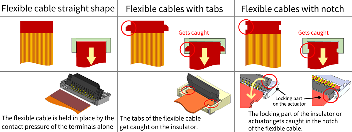
Changes in FPC/FFC (Flexible Cable) Shape
Previously, straight shapes were common, but they were improved to strengthen the horizontal flex retention force, and specifications with tabs and notches were added. This also improved the strength of the flexible cable.
Aiming to Reduce Work Hours
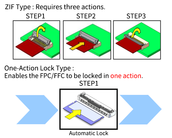
Mating completed in only one action
Previously, FPC/FFC connectors with locking features required a locking operation before and after inserting the FPC/FFC, which typically required manual assembly by operators.
That's why we developed the one-action locking type connector, which automatically locks with just one action of inserting the FPC/FFC, providing excellent workability and reducing assembly man-hours by one-third.
Additionally, manufacturing sites are seeing an increase in automation of processes using industrial robots, and Kyocera's one-action locking type connectors are also compatible with the automation of processes using industrial robots.
Development of High-Speed Transmission Compatible FPC/FFC Connectors

Automobiles are evolving year by year. For example, the performance of in-vehicle devices, such as Advanced Driver Assistance Systems (ADAS) and connected cars, is constantly improving. Many sensors are installed in cars, and huge amounts of data are now exchanged at high speeds.
As a result, connectors mounted in in-vehicle devices are also required to support high-speed transmission.
Given this background, connectors suitable for In-Vehicle Infotainment (IVI), in-vehicle cameras, radar, etc., are being developed that are capable of operating under harsh conditions such as vibration and high temperatures, as well as high-speed transmission.
High-speed transmission compatible FPC/FFC Connectors Product search
Comprehension Test
Q1.Which of the following is the traditional method of mounting a connector's solder terminals into holes in a circuit board?
(1) Through hole (2) DIY (3) SMT
Q2.What is the name for a locking style that has recently become popular, in which the actuator is on the opposite side to the FPC/FFC insertion port?
(1) Back flip (2) Non-ZIF (3) Front flip
Answers (Click to Check)
- A1. (1) Through hole
- A2. (1) Back flip
List of Connector Trivia Articles
vol.5 Evaluation Test (Basics)
vol.6 Evaluation Tests (Special Edition)
vol.7 The History of Kyocera's FPC/FFC Connectors
vol.8 Evolution of FPC/FFC Connectors
vol.9 Basic Knowledge of Board to Board Connectors
vol.10 Learn more about Board to Board Connectors ~Various Features~
vol.11 Basic Knowledge of Plating
Related Links
FPC/FFC Connectors Product Search Page
The Important Information/Disclaimer is incorporated in the catalog and/or this page by reference and should be reviewed in full before placing any order or inquiry.

