
FAQ
Search by keyword
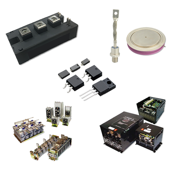
Power Semiconductor Devices
When considering dissipation with constant energy, I2・t is mainly used for fuses, high current products, and etc.
On the other hand, I2・√t is used when considering dissipation with constant temperature rise. In the case of semiconductors, thermal destruction does not occur when energy reaches a certain level, but it is thought that the phenomenon occurs when the temperature of the Si chip reaches a certain temperature. In that sense, I2・√t, calculating with specified temperature rise, is a more realistic and useful calculation method.
There is I2 in both methods, which means that the property of the semiconductor is lost in the large current region, it becomes a mere resistance, and if the resistance is r, the loss becomes I2r. In other words, I2 represents the loss. Therefore, it is a concept that I2・t defines the current resistance when the energy is constant, and I2・√t is to keep the temperature rise constant.
All values except for the graph of Junction capacitance vs. Reverse Voltage of SBD products are maximum values, which are guaranteed. Graphs of Junction capacitance vs. Reverse Voltage show typical values (TYP). The curves of the average forward current rating are formed by connecting points where the junction temperature reaches 150℃.
It indicates the forward current tolerance in steady state.
*Transient current flows (overload current, short pulse surge current) are excluded.
When the root-mean-square forward current is within the guaranteed values in Specifications, it is usable.
However, even if the current is within the guaranteed values, it may not be possible to use due to heat generation in the heat radiation environment and usage conditions.
The followings are recommended storage conditions for our power device products:
[Before unpacking]
Storage temperature: 5 to 35℃ / Storage humidity: 45 to 70% RH
MSL standards are defined for SMDs to be reflow-soldered, and all Kyocera products are MSL: 1. (No need for damp proof packing)
It depends on duty of the current flow.
If it is a square wave with 2A peak current and the duty is 50% or less, the average current becomes 1A or less, which is within the range of our guarantee. But if the duty is more than 50% and the average current exceeds the guaranteed value, which is out of the guaranteed range and it is impossible to be used. Additionally, please make sure that the peak current shall not exceed the maximum surge forward current.
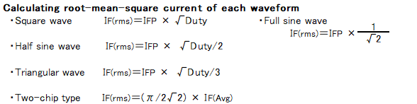
●Calculating average forward current of each waveform
- Square wave IF(Avg.) = IFP × Duty
- Half sine wave IF(Avg.) = IFP × {(2×Duty)/π}
- Triangular wave IF(Avg.) = (IFP/2)×Duty
Please avoid connect them directly. It is necessary to devise the wiring pattern and to examine the connection method so that the equal wiring reactor and series resistance can be expected. Please use products of same characteristics, such as ones in a manufacturing lot or unit of purchase. Characteristics of a device are closely related to temperature, and temperature unbalance causes current unbalance on products connected in parallel. To avoid it, it is effective to attach them closely or attach them to the same fin to equalize the element temperature.
The recommended range of mounting torque is between 0.4 and 0.8 Nm.
It would be difficult to secure voltage balance in two high-speed FRDs connected in series directly (Connection where voltage protection is not coordinated). Especially for the commutation surge voltage in high-speed switching, shared voltage varies largely due to difference in reverse recovery characteristics of the two devices. Thermal influence of other components and exoergic environment also affect the difference largely. Therefore, it is possible that 100% of voltage would be applied to one device.
In order to suppress such differences, it is necessary to add a voltage dividing capacitor to each device to share the differences. There is no specified capacitance value for such voltage dividing capacitors because the value varies depending on the operating conditions. It is necessary to make sure whether the voltage can be surely shared by the capacitors so that their capacitances could be between several tens pF and several hundreds pF.
Ripping can be suppressed by these capacitors. In order to divide the steady reverse voltage in half, resistors in parallel are also required.
That is to say, adding capacitors or resistors is an only way to balance voltage. The point is that adding a resistor or a capacitor is an only way to get the voltage balance.
When connecting one-chip type elements such as axial type products or miniature SMD products, 1:0.6 (62.5% : 37.5%) would be an approx. value as a general theory. Since two-chip in an element such as represented by the TO-220 type is a package and has good heat balance, the good flow dividing ratio would be 1:0.8 (55.6% : 44.4%).
In past days, surge current capability of a discrete diode had been considered to follow the I2t-constant law, as is the case with current fusing phenomenon. However, for more accurate estimation, the I2√t-constant law is preferable.
Therefore, guaranteed values for higher current products like as diode modules are calculated by I2・t , and lower current products like as discrete diodes should be calculated by I2√t. Even in this case, the resistance does not increase without limit, and the value at 100 μs is considered as the upper limit value for energization of 100 μs or less. In the case of a few micro seconds of electricity energizing time and a large duty, a limit could be caused due to the root mean squared value.
●Calculating formula for allowable current:
I2√t =(IFSM/√2)2× √10ms
IFSM: Surge forward current resistance value shown in Specifications or catalogues
t: Current pulse duration (100μs = 0.0001s at minimum)
The allowable current "I" can be obtained by substituting each value into the above formula. However, it would be corrected due to waveforms and energizing frequency.
Square waveform: I itself Triangular waveform: I×√3 Half sine wave: I×√2
- One shot current pulse: Current forcing only once in the circuit during the lifetime
The calculated value as above - A few current pulses in a day: Irregular and long-interval current pulses when the power turns on etc.
Half of the calculated value as above - Energizing continuously: Continuous energization
A quarter of calculated value as above
RECT is initial letters of RECTANGLE and means square waveform. It represents the conduction angle when one cycle is 360 °.
e.g.) Duty 50% = RECT 180°, Duty 25% = RECT 90°
Electronic Components Product Category
 Contact & Support


Search by part number
Search by keyword
Search by category
-
- SAW Devices
-
- Power Semiconductor Devices
-
- Power Semiconductor Devices
- Discretes General Rectifier Diodes
- Discretes Fast Recovery Diodes(FRD)
- Discretes Schottky Barrier Diodes(SBD)
- Discretes Avalanche Guaranteed Schottky Barrier Diodes
- High-power Devices General Rectifier Diodes Stud type
- High-power Devices General Rectifier Diodes Flat type
- High-power Devices Fast Recovery Diodes Stud type
- High-power Devices Thyristor Flat type
Discretes Diodes
Power Modules
High-power Devices
Stacks
Units
Advanced KYOCERA AVX Components
Search by Applications
Distributor Inventory Search
Please enter the model name of Kyocera. You can search up to 3 types at the same time.