FAQ
Search by keyword
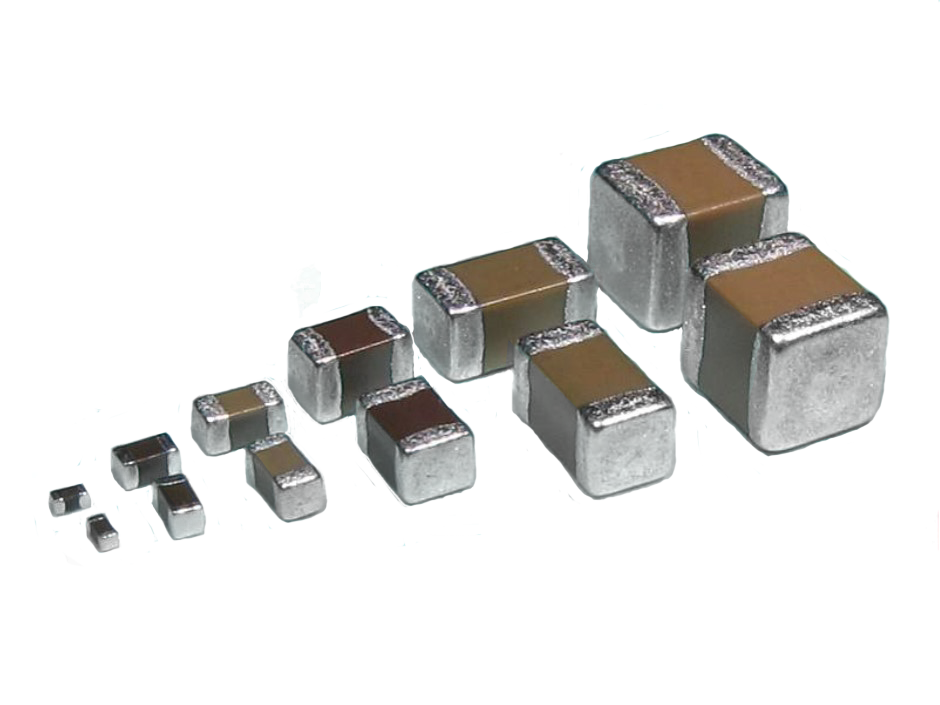
Capacitors
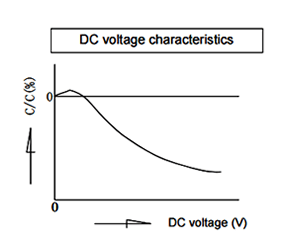
The capacitance of a capacitor changes depending on the DC voltage applied. Select a capacitor considering the DC voltage characteristics of the DC circuit in which the capacitor is used. The capacitance of ceramic capacitors might change sharply depending on the applied voltage. (See figure)
Confirm the followings in order to ensure desired capacitance.
- Confirm whether the capacitance change according to the applied voltage is within an allowable range or not.
- Regarding DC voltage characteristics, capacitance decreases as voltage increases, even if the applied voltage is below the rated voltage. Therefore, when a capacitor is used in a circuit with a narrow range of capacitance change allowance like a time constant circuit, it is recommended that the capacitance is within the allowable range under operating voltage.
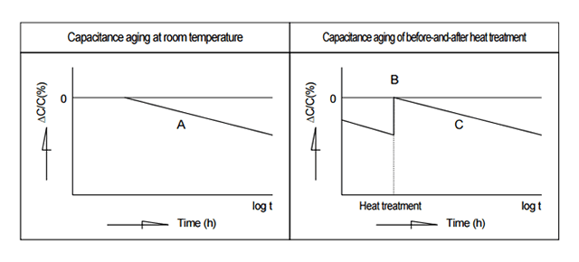
High dielectric constant ceramic material, when left in room temperature without any bias, has tendency to decrease its capacitance almost linearly to logarithmic time. This phenomenon is caused by the dielectric ceramics to transfer to more stable phase, and these are inevitable characteristics. Therefore, it is suggested to consider the capacitance change with time when using capacitors in circuits such as time constant circuit.
Most ceramic dielectrics used for ceramic capacitors have ferroelectric characteristics, and exhibit a curie temperature. Above this temperature, the dielectrics have a highly symmetric cubic crystal structure whereas below the curie temperature, the crystal structure is less symmetrical. Although in single crystals this phase transition is very sharp, in practical ceramics it is often spread over a finite temperature range. In all cases it is linked with a peak in the capacitance/temperature curve.
Under the influence of thermal vibration, the ions in the crystal lattice continue to move to positions of lower potential energy for a long time after the dielectric has cooled down below the curie temperature. This makes capacitance aging, whereby a capacitor's capacitance continually decreases. (Line A in the below graph) However, if the capacitor is heated to a temperature above the curie temperature, de-aging takes place and the capacitance lost through aging is regained. (B point in the below graph) The aging recommences when the capacitor cools down below its curie temperature. (Line C in the below graph)
This is a phenomenon of shifting to a lower energy state by which the ceramic dielectric becomes more stable.Therefore, take capacitance aging into consideration when using a capacitor with Class 2 or Class 3 ceramic dielectrics for a circuit with a narrow range of allowable capacitance change, such as a time constant circuit.
Since the effects of this aging can be reversed, a dielectric's capacitance can be returned to its original value by subjecting it to a higher temperature than its Curie point, e.g. 125°C for BaTiO3. The phenomena can been noticed immediately after soldering or after reworking/repair with a soldering iron.
Heat stress during rework may possibly be reduced by using a spot heater (also called a "blower") rather than a soldering iron.
General Instruction
When capacitors are reworked using soldering irons beyond the limits stated in the catalogs or product specifications, cracks may occur in the capacitors due to thermal stress and insulation resistance may deteriorate.
When lead-free solder which has a higher melting point (liquid phase temperature of over 200 °C) is used, the risk of cracks is higher due to the larger thermal stress in the capacitor induced if rapid cooling or heating and partial heating occur during reworking.
Do not touch the tip of a soldering iron to the termination electrode of a capacitor.
Reworking using a spot heater may suppress the occurrence of cracks in the capacitor compared to using a soldering iron. A spot heater can heat up a capacitor uniformly with a small heat gradient which leads to lower thermal stress caused by quick heating and cooling or localized heating.
Moreover, where ultra-small capacitors are mounted close together on a printed circuit board, reworking with a spot heater can eliminate the risk of direct contact between the tip of a soldering iron and a capacitor.
Repair Conditions
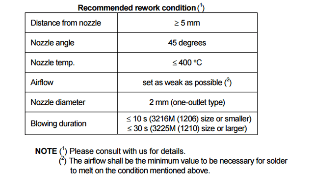
If the blower nozzle of a spot heater is too close to a capacitor, a crack in the capacitor may occur due to heat stress. Below are recommendations for avoiding such an occurrence.
Keep more than 5 mm between a capacitor and a spot heater nozzle.
The blower temperature of the spot heater shall be lower than 400 °C.
The airflow shall be set as weak as possible.
The diameter of the nozzle is recommended to be 2 mm (one-outlet type). The size is standard and common.
Duration of blowing hot air is recommended to be 10 s or less for 3225M size or smaller capacitors, and 30 s or less for 3216M size or larger capacitors, considering surface area of the capacitor and melting temperature of solder.
The angle between the nozzle and the capacitor is recommended to be 45 degrees in order to work easily and to avoid partial area heating.
As is the case when using a soldering iron, preheating reduces thermal stress on capacitors and improves operating efficiency.
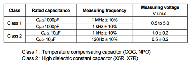
Measure the capacitance under the conditions specified in the product specifications.
Some measuring equipment may not be able to apply the required measuring voltage and the measured value will be underestimated, when capacitance is high. Measuring equipment with Auto Level Control (ALC) function is recommended.
Most of the causes of difference in measured capacitance among each measuring equipment result from difference in actual voltage applied by each measuring equipment even if the same measuring voltage is set up.
Since higher capacitance makes smaller impedance in capacitors, it shall not disregard the influence of the voltage drop by voltage divider with the output resistance of measuring equipment.
The measuring equipment, which has the function to adjust to the measuring voltage automatically, is recommended for the measurement of a high capacitance capacitor. And, when the measuring equipment without the ALC function is used, it is recommended to check and adjust the measuring voltage by a voltmeter.
The soldering conditions (preheating temperature, soldering temperature and their durations) shall be within the limits in the catalogs or product specifications.
When the capacitors are used exceeding the limits given in the catalogs or product specifications, cracks may occur in the capacitors and the reliability may deteriorate, especially the rapid temperature changes and partial heating during soldering may cause cracks.
Generally recommended temperature conditions for reflow soldering is as follows:
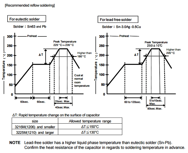
When the capacitors are soldered under long duration or high temperature, the dissolution of electrode (leaching), deterioration of adhesion (shear strength) and capacitance decrease may occur.
Take into consideration tombstone phenomenon (also called "Manhattan phenomenon") for 3216M size or smaller capacitors when the soldering is not proper.
The tombstone phenomenon can be avoided by taking the following measures:
- - reducing land dimensions
- - applying adequate preheating
- - optimizing solder amount
- - ensuring accurate placement
- providing equal heating to both terminations during soldering
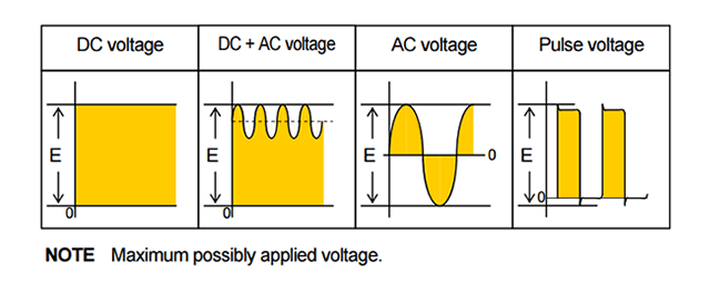
Voltage which is applied to the capacitor should not exceed the rated voltage given in the specifications.
When AC voltage is superimposed on DC voltage, the zero-to-peak voltage shall not exceed the rated voltage.
When AC voltage or pulse voltage is applied, the peak-to-peak voltage shall not exceed the rated voltage.
Applying overvoltage to a capacitor may cause dielectric breakdown and result in a short circuit.
The duration until dielectric breakdown depends on the applied voltage and the ambient temperature. Abnormal voltage (surge voltage, static electricity, pulse voltage, etc.)shall not exceed the rated voltage. When pulse voltage with a very short rising time or AC voltage of a high frequency is applied to capacitors, even though the voltage is less than or equal to the rated voltage, the reliability of the capacitor may be influenced.
The following storage conditions are recommended unless otherwise specified by the detailed specification.
- *Recommended temperature range: 5 to 40°C
- *Recommended humidity range: 20 to 70% RH
See JIS C 60721-3-1, class 1K2 for other climatic conditions.
- High temperature and high humidity environment may affect capacitor's solderability because they accelerate terminal oxidization. They also deteriorate performance of taping and packaging. Therefore, the following storage periods are recommended.
- For SMD capacitors, use within 6 months.
- When capacitors are stored for a period longer than specified, confirm the solderability of the capacitors prior to use.
- Store capacitors without opening their unit bags. Keep them in the same package as shipped.
- Even though the storage period is short, do not exceed the specified atmospheric temperature and humidity conditions.
- Corrosive gasses in the air or atmosphere may result in deterioration of the reliability, such as poor solderability of the terminal electrodes or lead wires of capacitors. Do not store capacitors where they will be exposed to corrosive gas (e.g. H2S,SO2,NO2,Cl2 etc.).
- In corrosive atmosphere, solderability might be degraded, and silver migration might occur to cause low reliability.
- Due to the dewing by rapid humidity change, or the photochemical change of the terminal electrode by direct sunlight, the solderability and electrical performance may deteriorate. Do not store capacitors under direct sunlight or dewing condition.
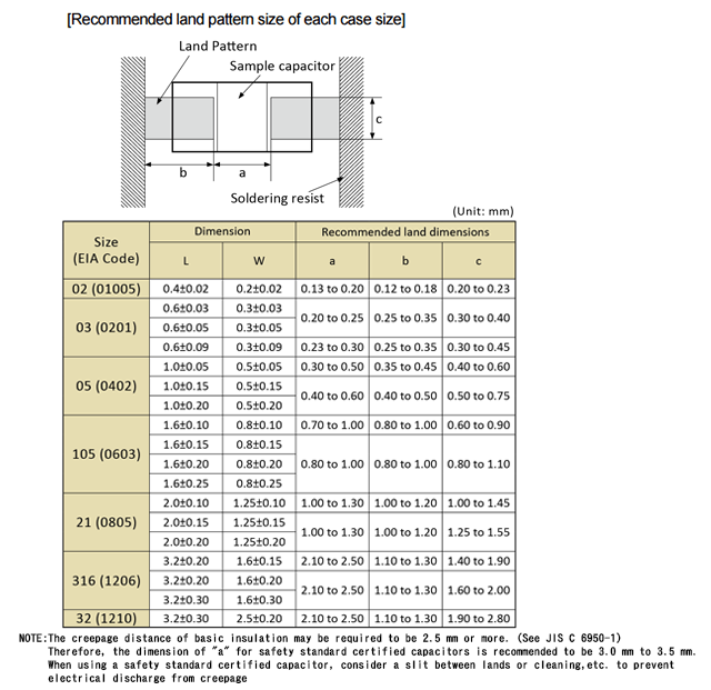
Since the amount of solder (fillet size) for mounting a capacitor on a printed circuit board influences the capacitor directly, sufficient consideration is necessary. Confirm the suitable land pattern size in order to decide the suitable amount of solder.
When the amount of solder is too much, stress on a capacitor increases. It may cause a crack in the capacitor. When a land design of a printed wiring board is considered, it is necessary to set up the form and size of the land pattern so that the amount of solder is suitable.
When the amount of solder is too little, the adhesion (shear) strength of the terminal electrode may be insufficient, and the capacitor may drop off from the printed wiring board. The reliability of the circuit may also be affected.
Recommendation for land pattern size with which the amount of solder does not become excessive
Although there is not a specification of ripple current for ceramic capacitors, it is recommended to confirm the following.
Confirm whether AC voltage and pulse voltage are continuously applied to the capacitor. Be sure to take into account self-heating when using DC capacitors for AC or pulse circuits. General capacitors are designed for DC use. When they are used in a circuit where AC or pulse voltage is applied, the current value may increase and the capacitors may short-circuited due to self-heating.
- For capacitors of Class 2, it is necessary to maintain the surface temperature shall not increase more than 20°C.
- For capacitors of Class 1, since the permitted temperature rise depends on the dielectric material, consult us about the details.
Note:
- Class 1 : Temperature compensating capacitor (C0G, NPO)
- Class 2 : High dielectric constant capacitor (X5R, X7R)
Self-heating of a capacitor depends on the dielectric material, the capacitance, the applied voltage, the frequency, the voltage waveforms and other factors. Moreover, the surface temperature may be affected by heat radiation related to the style of the capacitor, the mounting method to the equipment and the ambient temperature.
Since self-heating affects the characteristics of capacitors when ambient temperature changes, even under the same voltage conditions, perform the confirmation of self-heating at room temperature (25 °C).
 Contact & Support


Search by part number
Search by keyword
Search by category
-
- SAW Devices
- Advanced KYOCERA AVX Components
Search by Applications
Distributor Inventory Search
Please enter the model name of Kyocera. You can search up to 3 types at the same time.