- Crystal Devices
What Are the Equivalent Circuit Constants of a Crystal Unit?


This page will explain the equivalent circuit and electrical characteristics of crystal units, which are important when designing a reference signal source.
Equivalent Circuit of Crystal Unit
The vibration (resonance phenomenon) of a crystal unit is represented by an electrical equivalent circuit.
The general equivalent circuit is as follows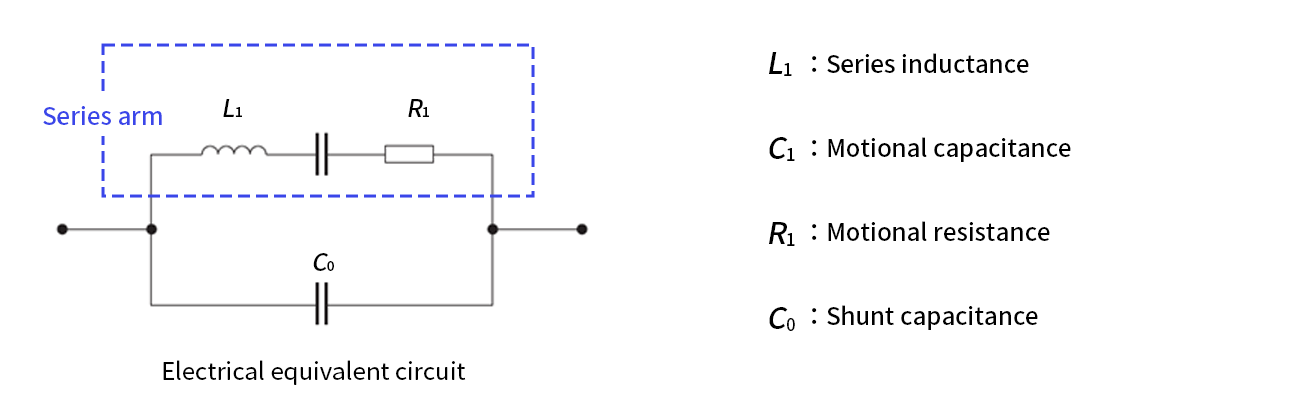
Keywords The Official Mascot of Kyocera’s Electronic Components: Eletan
Click here to learn more about Eletan
- Motional inductance: L1
This is the inductance of the series arm of an equivalent circuit; a larger value results in a higher Q and increased oscillation stability. - Motional capacitance: C1
The larger this value, the larger the frequency variation with respect to the change in load capacitance.
Therefore, C1 may be designed to be small for oscillators with high stability, or C1 may be designed to be large for VCXOs, where a large change in frequency is desired. - Motional resistance: R1
The resistance of the series arm in the equivalent circuit is the resistance where the conductance is maximized in the admittance circle diagram.
This is the loss resistance when the oscillator vibrates, and generally the smaller this value is, the better the oscillator will be. - Shunt capacitance: C0
This is the capacitance between the electrodes of a crystal unit, and it is determined by the thickness and area of the electrodes of the unit.
These equivalent constants are subject to variation depending on the thickness and area of the electrodes of the unit. Generally, the smaller the crystal unit, the smaller C1. Additionally, L1 and C1 are inversely proportional to each other.
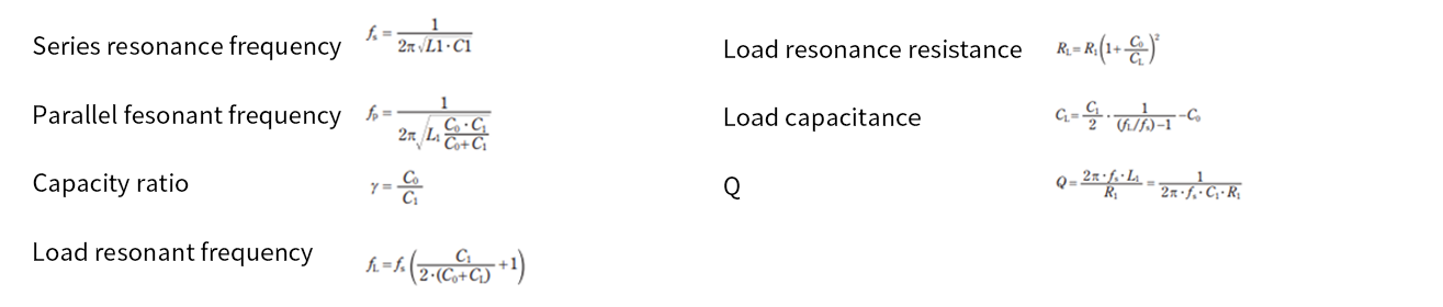
Items Calculated From Equivalent Constants and Load Capacitance
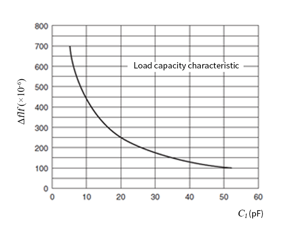
- The resonant frequency of a crystal unit changes depending on the load capacitance (CL).
The formula for fL shows that the frequency changes when the load capacitance connected to the crystal unit is changed. The smaller the CL, the greater the change in frequency. - The resonance resistance of a crystal unit changes depending on load capacitance (CL).
The formula for RL shows the change in impedance when a load capacitance is connected. As CL decreases, the impedance of the crystal unit increases. - The oscillation frequency fL can be used to determine the circuit's load capacitance (CL).
As mentioned previously, the series resonance frequency of a crystal unit changes in accordance with the load capacitance CL of the oscillation circuit. In practical oscillation circuits, the load capacitance CL is adjusted using components such as trimmer capacitors to fine-tune the oscillation frequency. The diagram on the right illustrates an example of load capacitance characteristics, and the slope of these characteristics varies depending on the frequency, shape, and overtone order of the crystal unit.
Providing Customers With Peace of Mind

To ensure customers can use our timing devices with peace of mind, Kyocera has established technical support centers around the world to provide circuit matching services.
Introducing Design Support by Circuit Matching Service
Benefits
- Stable oscillation with higher gain margin.
- Improved start-up time of oscillation.
- Quick and flexible design support.

List of Basic Knowledge About Timing Devices Articles
vol.1 What is Crystal Unit Matching?
vol.2 What are the Equivalent Circuit Constants of a Crystal Unit?
The Important Information/Disclaimer is incorporated in the catalog and/or this page by reference and should be reviewed in full before placing any order or inquiry.
Related Keywords
Technical information View All


 Contact & Support


Search by part number
Search by keyword
Search by category
-
- SAW Devices
- Advanced KYOCERA AVX Components
Search by Applications
Distributor Inventory Search
Please enter the model name of Kyocera. You can search up to 3 types at the same time.