- Capacitors
--Development of Highly Reliable MLCC-- Evaluation and Analysis Technology Visualizes Areas of Deterioration


As electronic devices become smaller and more functional, multilayer ceramic chip capacitors (MLCCs) are becoming smaller and thinner. This requires the development of highly reliable MLCCs that can operate under harsh conditions, such as higher electric field strength and higher temperatures than ever before.
We will introduce the evaluation and analysis technology that visualizes degradation areas, which is one of the essential technologies/material technologies, process technologies, and evaluation and analysis technologies necessary for developing high-reliability MLCCs
Overview
In the development of MLCCs, if the factors that determine the lifespan of MLCCs under high temperature and high electric field could be identified and further visualized, it would lead to more accurate material design. Therefore, in order to develop highly reliable MLCCs with long lifespans, we attempted to visualize the degradation points and identify the causes of degradation during the dielectric degradation process.
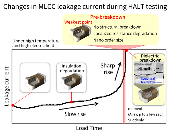
In the case of dielectric breakdown, it is relatively easy to identify the point of breakdown, but when the structure has been destroyed to the point that cracks form or Ni electrodes melt, it is very difficult to identify the cause of degradation. Therefore, it is important to visualize the degradation point just before dielectric breakdown, where no structural breakdown has occurred.
Keywords The Official Mascot of Kyocera’s Electronic Components: Eletan
Click here to learn more about Eletan
What is HALT testing?
It is an abbreviation for "Highly Accelerated Life Test." HALT testing is a type of reliability evaluation that can accelerate deterioration under conditions that are more severe than the actual usage environment, and is therefore used to predict life spans and evaluate areas of deterioration.
Efforts to Visualize Deteriorated Areas Prior to Dielectric Breakdown
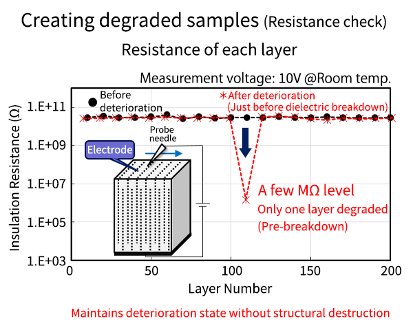
To identify the location of dielectric degradation without causing structural breakdown, we focused on the rate of current change. First, we stopped the HALT test just before the rate of current change suddenly increased and led to breakdown, and intentionally created a degraded sample. Then, we scraped off the terminal electrodes on the MLCC end faces and measured the resistance with the internal electrodes exposed. As a result, we were able to identify the locally degraded layer without causing dielectric breakdown.
Next, we investigated the degraded areas on the MLCC surface using the following procedure.
- Processing close to the deteriorated area
- Detecting low-resistance deteriorated areas using the IR-OBIRCH method
- Observation of deteriorated areas: Cross-sections of the detected deteriorated areas are processed using FIB. The microstructure of the deteriorated areas is observed using a scanning electron microscope (SEM) or transmission electron microscope (TEM) to investigate differences from normal areas.
Examples of Visualizing the Microstructure of Deteriorated Areas and Analyzing Wear-out Failure Areas
- Short-term failure side: It was found that there are cases where short-term failures are caused by localized thinning of the dielectric part.
- Wear-out failure area: Non-uniformity in particle size was confirmed inside the porcelain (area indicated by white arrow). This result suggests that non-uniformity inside the porcelain causes variation in lifespan.
Next, the microstructure of the deteriorated area was quantified and correlation with lifespan was examined.
Analysis of the relationship between microstructure in dielectric and lifespan
When two types of MLCCs (Lot A and B) with different firing temperatures were compared, it was presumed that the difference in firing temperature caused changes in the microstructure, which contributed to the lifespan.
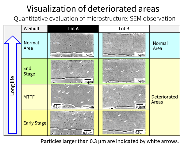
To investigate the relationship between the lifespan and microstructure in Lot A and B, samples immediately before dielectric breakdown were prepared at each stage of short life, MTTF, and long life, and the areas of deterioration were identified and observed.
SEM observation results
When the deteriorated areas were observed with an SEM immediately before destruction, no coarse particles were found in the normal areas of both Lots A and B.
However, multiple coarse particles measuring 0.3 μm or larger were found in the deteriorated areas, as indicated by the white arrows in the photograph.
First, we compared the number of coarse particles, but there was no clear correlation with each life level. Since the correlation cannot be explained simply by the number of coarse particles, we investigated the number of particles per dielectric layer as another indicator. As a result of investigating the correlation between the minimum number of particles per unit thickness between dielectric layers and the HALT life at 170°C and 45V, we confirmed a generally good correlation between the minimum number of particles per unit thickness of the dielectric and the life, and found that the greater the minimum number of particles and the closer it is to the normal area, the longer the life.
Therefore, by visualizing the deteriorated areas, we were able to clarify that a local decrease in the number of particles is one of the important factors that accelerates deterioration and shortens the life.
Furthermore, when the lifetime is compared with, for example, 5 particles per micron, the relationship between the lifetime and the number of particles is different, which is an interesting result that suggests that not only the number of particles between dielectric layers but also other factors may be involved.
Therefore, we investigated the elemental composition distribution of coarse particles in the degraded region using TEM-EDX.
TEM observation results for deteriorated areas
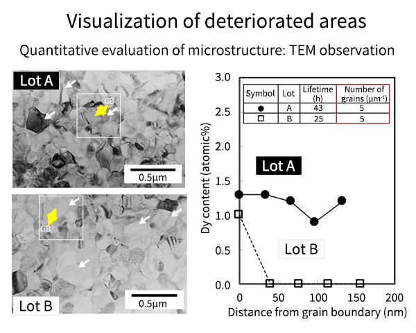
Samples from both lots A and B in which the number of particles between the dielectric layers was five were extracted and evaluated (red frame in the graph on the right of the image). As with the SEM observations above, multiple coarse particles of 0.3 μm or more were confirmed in the deteriorated areas, as indicated by the white arrows.
For these coarse particles, we performed an EDX semi-quantitative analysis of the rare earth element Dy from the grain boundaries to within the grains (graph on the right of the image).
The yellow arrow in the photo is a representative example of a coarse particle. Dy is one of the elements added in this prototype, and is said to have the effect of suppressing the movement of oxygen vacancies. In both Lots A and B, Dy is present in high concentrations near the grain boundaries, but within the grains, diffusion of Dy was confirmed even at positions several tens of nm away from the grain boundaries in Lot A, whereas in Lot B, almost no diffusion of Dy was observed even at positions 50 nm away from the grain boundaries. A similar tendency was confirmed for other coarse particles.
This suggests that in addition to the number of smallest particles in the dielectric layer contributing to the lifetime, the diffusion and solid solution of rare earth elements in the coarse particles at the degradation site, i.e., the shell state, also contribute to the lifetime.
Conclusion
- Established a method to visualize the deteriorated part without dielectric breakdown while maintaining the deteriorated part.
- Visualization of deteriorated wear failure locations
Non-uniformity within the dielectric was identified as a cause of wear failure. - In addition, when normalized by the number of particles per dielectric thickness, there is a correlation with lifetime, further suggesting that the diffusion state of the additive elements within the larger particles also contributes to the lifetime.
These results show that reducing the amount of coarse particles actually extends the lifespan of parts that fail due to wear.
In this way, we have created an evaluation and analysis technology that makes previously invisible phenomena visible.
Data is based on research by Kyocera.
Kyocera will continue to strive toward ever higher quality MLCCs
utilizing failure analysis technology to promote higher reliability dielectric materials.

Related Links
Capacitors Catalog (PDF/1.4MB)
Click Here for Find All MLCC Products
The Important Information/Disclaimer is incorporated in the catalog and/or this page by reference and should be reviewed in full before placing any order or inquiry.
Related Keywords
Technical information View All


 Contact & Support


Search by part number
Search by keyword
Search by category
-
- SAW Devices
- Advanced KYOCERA AVX Components
Search by Applications
Distributor Inventory Search
Please enter the model name of Kyocera. You can search up to 3 types at the same time.