TCF10F60 2.Production

 Stock Check
Application
- Power supplies
- Industrial Equipment
Specifications
| Series | TT |
|---|---|
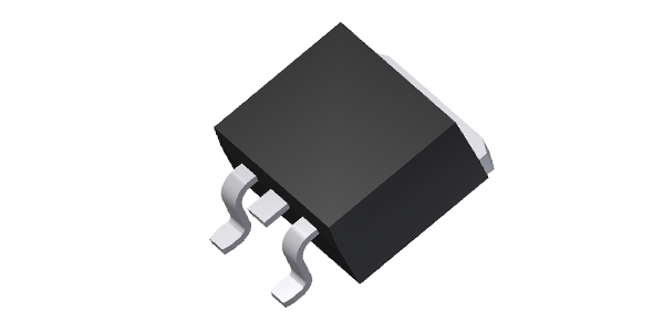
| Outline |
TO-263(D2pak)
|
| VRRM [V] | 600V |
| Io [A] | 10.0A |
| IFSM [A] | 80.0A |
| IR [mA] | 0.020mA |
| VFM [V] | 1.70V |
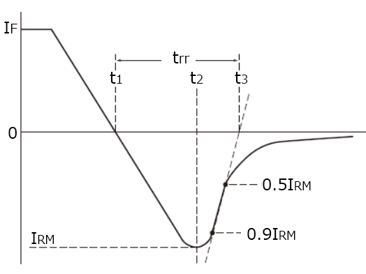
| trr [ns] | 40.0ns |
| Operating Temperature Range | -55℃ ~ 175℃ |
| Rth(j-c) [°C/W] | 3.00°C/W |
| Connection type | B |
| Packaging style | Reel |
| Quantity per Package | 1000 |
| Weight | 1.400g |
Packaging Specifications
| Packaging style | Reel |
|---|---|
| Quantity per Package | 1000 |
| Weight | 1.400g |
Engineering Documents
Product Specification / Drawing
 TCF10F60-file.pdf (1345.53KB)
FAQ
View AllIt would be difficult to secure voltage balance in two high-speed FRDs connected in series directly (Connection where voltage protection is not coordinated). Especially for the commutation surge voltage in high-speed switching, shared voltage varies largely due to difference in reverse recovery characteristics of the two devices. Thermal influence of other components and exoergic environment also affect the difference largely. Therefore, it is possible that 100% of voltage would be applied to one device.
In order to suppress such differences, it is necessary to add a voltage dividing capacitor to each device to share the differences. There is no specified capacitance value for such voltage dividing capacitors because the value varies depending on the operating conditions. It is necessary to make sure whether the voltage can be surely shared by the capacitors so that their capacitances could be between several tens pF and several hundreds pF.
Ripping can be suppressed by these capacitors. In order to divide the steady reverse voltage in half, resistors in parallel are also required.
That is to say, adding capacitors or resistors is an only way to balance voltage. The point is that adding a resistor or a capacitor is an only way to get the voltage balance.
All values except for the graph of Junction capacitance vs. Reverse Voltage of SBD products are maximum values, which are guaranteed. Graphs of Junction capacitance vs. Reverse Voltage show typical values (TYP). The curves of the average forward current rating are formed by connecting points where the junction temperature reaches 150℃.
MSL standards are defined for SMDs to be reflow-soldered, and all Kyocera products are MSL: 1. (No need for damp proof packing)
The followings are recommended storage conditions for our power device products:
[Before unpacking]
Storage temperature: 5 to 35℃ / Storage humidity: 45 to 70% RH
Related Glossary
View AllPN type junction rectifying device. Diodes suitable for rectifying high frequency power supply with short reverse recovery time (trr).
Related Products Discretes Fast Recovery Diodes(FRD) FRD/SBD Modules
[Diode]Allowable peak reverse voltage repetitively applicable to diode.
[Thyristor]Allowable peak reverse voltage repetitively applicable between anode and cathode.
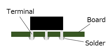
A method of mounting components on a printed circuit board (PCB) by inserting component leads to be soldered into through-holes of a PCB and dipping it into a solder bath to mount the components.
[Diode]Allowable peak reverse voltage repetitively applicable to diode.
[Thyristor]Allowable peak reverse voltage repetitively applicable between anode and cathode.
A two-terminal semiconductor device which conducts current in one direction, i.e. from anode to cathode, also called a rectifier.
 Contact & Support


Search by part number
Search by keyword
Search by category
-
- SAW Devices
-
- Power Semiconductor Devices
-
- Power Semiconductor Devices
- Discretes General Rectifier Diodes
- Discretes Fast Recovery Diodes(FRD)
- Discretes Schottky Barrier Diodes(SBD)
- Discretes Avalanche Guaranteed Schottky Barrier Diodes
- High-power Devices General Rectifier Diodes Stud type
- High-power Devices General Rectifier Diodes Flat type
- High-power Devices Fast Recovery Diodes Stud type
- High-power Devices Thyristor Flat type
Discretes Diodes
Power Modules
High-power Devices
Stacks
Units
Advanced KYOCERA AVX Components
Search by Applications
Distributor Inventory Search
Please enter the model name of Kyocera. You can search up to 3 types at the same time.