Evaluation of strain in processes
When bending stress is applied to a component-mounted printed wiring board, a crack may occur at an edge of
termination electrode of a capacitor. When a crack occurs in a capacitor, even if the electrical
characteristics are initially fine, the lifetime of the part becomes remarkably shorter.
It is necessary to make bending stress of the printed circuit board as small as possible. Design the printed
circuit board and its process to minimize the strain amount.
Strain evaluation
- ・Necessity of evaluation of strain
When bending stress is applied to a printed circuit board, the convex surface of the printed circuit board expands along the direction of surface expansion. This expansion is tensile strain. The strain is transferred from the land to the bottom face of a capacitor through the solder and the termination electrodes. The strain generates tensile stress which concentrates at the edge of the termination electrode. Because the ceramic is a brittle material, the concentrated stress may cause a crack under the termination electrode.
Printed circuit board bending occurs during board cropping too. It is difficult to measure bending depth at the process. Generally, strain on the surface of a printed circuit board is measured by a strain gauge.
Keep deformation low by monitoring strain. - ・Notes for evaluation of strain
- 1) Strain measurement location
When evaluating a strain of a printed wiring board on which a capacitor is mounted, remove the capacitor first and then measure a strain at the position where the capacitor was mounted. Measuring the strain near the mounted capacitor without removing it would give an erroneous value due to the stiffening effect on the board from the capacitor's rigidity.
The condition of the printed wiring board, such as the material of surrounding components, the solder material, and its amount, should be similar to an actual one for proper evaluation. - 2) Usage of strain gages
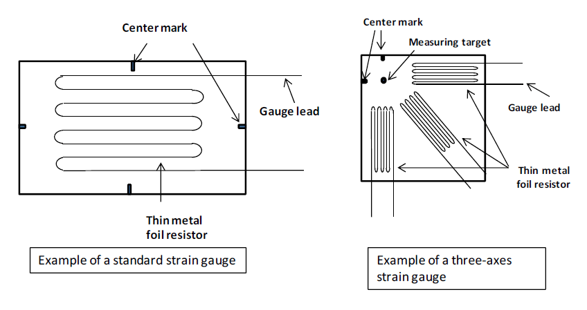
The strain in the actual process may be generated in any 360-degree direction. Therefore, it is recommended to use a three-axis strain gauge. When using a three-axis strain gauge, the center of the gauge should be set on the position to be measured.
- 1) Strain measurement location
Distortion dimension
- ・Principle of measurement
Generally, when metal is deformed by external stress, the electrical resistance of the metal is changed. The electrical resistance is in inverse proportion to a cross-sectional area and is in proportion to the length. Strain gauge is subject to this principle. When a strain gauge consisted of thin metal foil resistor(s) attached onto an object and the object is deformed, the resistor is deformed, causing its electrical resistance to change according to the above principle and the strain can be calculated from the resistance change using the strain factor.
An example of reducing crack occurrence using strain evaluation
An example of train gauge attachment is shown in the following figure.
Strain of a printed wiring board was measured in each process and it was found that the largest strain
occurred in the cropping process.
In order to decrease the strain, a slit was extended to the vicinity of the capacitor's mounting position.
This design change suppressed the occurrence of cracks in capacitors.
Safety Application Guide for Multilayer Ceramic Chip Capacitors All Lists
 Contact & Support


Search by part number
Search by keyword
Search by category
-
- SAW Devices
- Advanced KYOCERA AVX Components
Search by Applications
Distributor Inventory Search
Please enter the model name of Kyocera. You can search up to 3 types at the same time.