- Crystal Devices
What Exactly Is Oscillator Jitter? (Part 1)

In this segment, we will define "oscillator jitter," a term that emerges during the evaluation of ICs and the design of circuits.
What is Jitter?
Jitter, as defined by a crystal oscillator, represents the deviation between the ideal waveform of a specific frequency and the waveform actually observed from the oscillator.
The jitter value is derived from the observation of this waveform deviation through various methods.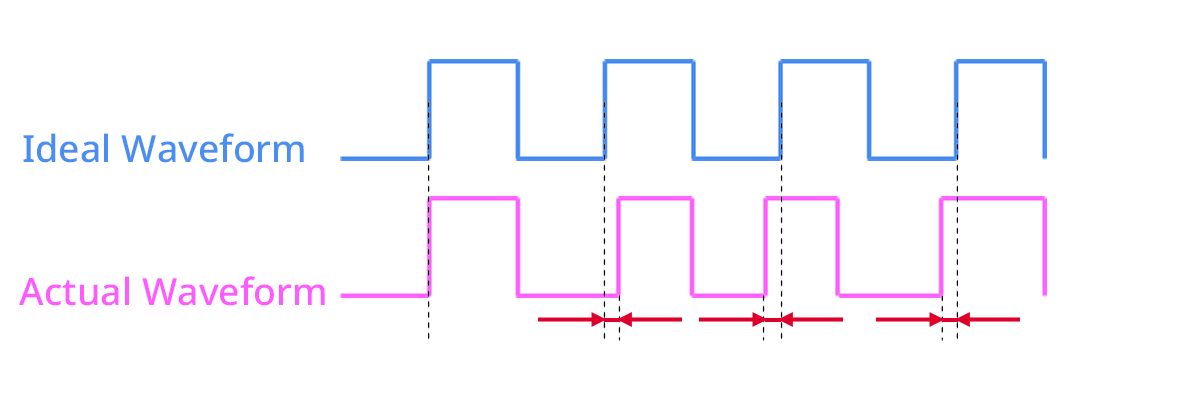
Jitter Types and Measurements
Jitter Types
There are many kinds of jitter.
Various terms are used, including period jitter, cycle-to-cycle jitter, phase jitter, RMS jitter, and 1σ (sigma) jitter. Generally speaking, when we say jitter, it often means period jitter or phase jitter. These differences also depend on how you measure jitter. First, let's take a look at the differences between jitter measurement methods and equipment.
Jitter Measurements
Measuring Instrument | Group | Features | Disadvantages |
|---|---|---|---|
Time Interval Analyzer (TIA) | Time Domain |
|
|
Digital Storage Oscilloscope (DSO) | Time Domain |
|
|
Signal Source Analyzer(SSA) | Freq. Domain |
|
|

List of Basic Knowledge About Timing Devices Articles
vol.1 What is Crystal Unit Matching?
vol.2 What Are the Equivalent Circuit Constants of a Crystal Unit?
vol.3 What Exactly Is Oscillator Jitter? (Part 1)
vol.4 What Exactly Is Oscillator Jitter? (Part 2)
The Important Information/Disclaimer is incorporated in the catalog and/or this page by reference and should be reviewed in full before placing any order or inquiry.
Related Keywords
Technical information View All

 Contact & Support


Search by part number
Search by keyword
Search by category
-
- SAW Devices
- Advanced KYOCERA AVX Components
Search by Applications
Distributor Inventory Search
Please enter the model name of Kyocera. You can search up to 3 types at the same time.