Reflow soldering
The soldering conditions (preheating temperature, soldering temperature and their durations) shall be within the limits in the catalogs or product specifications.
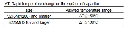
When the capacitors are used exceeding the limits given in the catalogs or product specifications, cracks may occur in the capacitors and the reliability may deteriorate, especially the rapid temperature changes and partial heating during soldering may cause cracks.
Generally recommended temperature conditions for reflow soldering is as follows:
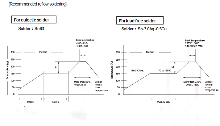
NOTE Lead-free solder has a higher liquid phase temperature than eutectic solder (Sn-Pb).
Confirm the heat resistance of the capacitor in regards to soldering temperature in advance.
When the capacitors are soldered under long duration or high temperature, the dissolution of electrode (leaching), deterioration of adhesion (shear strength) and capacitance decrease may occur.
Take into consideration tombstone phenomenon (also called "Manhattan phenomenon")
for 3216M size or smaller capacitors when the soldering is not proper.
. The tombstone phenomenon can be avoided by taking the following measures:
- reducing land dimensions
- applying adequate preheating
- optimizing solder amount
- ensuring accurate placement
- providing equal heating to both terminations during soldering
Mount the capacitor as soon as possible after applying solder paste.
If the interval between applying solder paste and mounting a capacitor is too long, solderability may decrease due to drying and hardening of the solder paste.
Use a suitable amount of solder to form a proper fillet shape.
Excess solder generates high contraction stress and thermal stress. As a result, cracking or breaking of the capacitor may occur. Insufficient solder results in deficient capacitor adherence to the printed wiring board, which may cause capacitor dropout or poor electrical connection which, in turn, may cause reliability to deteriorate. Typical shapes of solder fillet are shown as follows
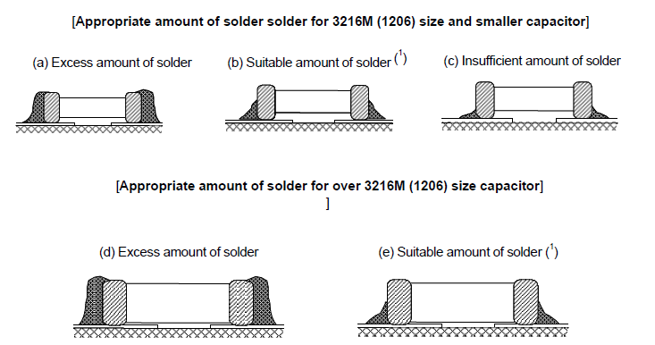
Note (1) Recommended fillet height: 1/3~2/3 of the thickness of capacitor or 0.5 mm, whichever is
smaller.
For the fillet height of very small size capacitors, please consult us.
Select an appropriate solder material referring the following notices.
Inappropriate materials can cause troubles such as solder balls.
- ・Sn-Zn solder may deteriorate the insulation resistance of capacitor under some operating environments.
Safety Application Guide for Multilayer Ceramic Chip Capacitors All Lists
 Contact & Support


Search by part number
Search by keyword
Search by category
-
- SAW Devices
- Advanced KYOCERA AVX Components
Search by Applications
Distributor Inventory Search
Please enter the model name of Kyocera. You can search up to 3 types at the same time.