
Soldering rework using a spot heater
Heat stress during rework may possibly be reduced by using a spot heater (also called a "blower") rather than a soldering iron.
General Instruction
When capacitors are reworked using soldering irons beyond the limits stated in the catalogs or product specifications, cracks may occur in the capacitors due to thermal stress and insulation resistance may deteriorate.
When lead-free solder which has a higher melting point (liquid phase temperature of over 200 ℃) is used, the risk of cracks is higher due to the larger thermal stress in the capacitor induced if rapid cooling or heating and partial heating occur during reworking.
Do not touch the tip of a soldering iron to the termination electrode of a capacitor.
Reworking using a spot heater may suppress the occurrence of cracks in the capacitor compared to using a soldering iron. A spot heater can heat up a capacitor uniformly with a small heat gradient which leads to lower thermal stress caused by quick heating and cooling or localized heating.
Moreover, where ultra-small capacitors are mounted close together on a printed circuit board, reworking with a spot heater can eliminate the risk of direct contact between the tip of a soldering iron and a capacitor.
Adjustment Conditions
If the blower nozzle of a spot heater is too close to a capacitor, a crack in the capacitor may occur due to heat stress. Below are recommendations for avoiding such an occurrence.
Keep more than 5 mm between a capacitor and a spot heater nozzle.
The blower temperature of the spot heater shall be lower than 400 ℃.
The airflow shall be set as weak as possible.
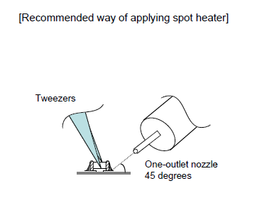
The diameter of the nozzle is recommended to be 2 mm (one-outlet type). The size is standard and common.
Duration of blowing hot air is recommended to be 10 s or less for 3225M size or smaller capacitors, and 30 s or less for 3216M size or larger capacitors, considering surface area of the capacitor and melting temperature of solder.
The angle between the nozzle and the capacitor is recommended to be 45 degrees in order to work easily and to avoid partial area heating.
As is the case when using a soldering iron, preheating reduces thermal stress on capacitors and improves operating efficiency.
Recommended rework condition (1)
| Distance from nozzle | ≧5 mm |
|---|---|
| Nozzle angle | 45 degrees |
| Nozzle temp. | ≦400 ℃ |
| Airflow | set as weak as possible(2) |
| Nozzle diameter | 2 mm (one-outlet type) |
| Blowing duration | ≦10 s (3216M (1206) size or smaller) ≦ 30 s (3225M (1210) size or larger) |
NOTE(1) Please consult with us for details.
(2) The airflow shall be the minimum value to be necessary for solder
to melt on the condition mentioned above.
Amount of solder should be suitable to form a proper fillet shape.
Excess soldering causes mechanical and thermal stress on a capacitor and results in cracks. Insufficient soldering causes weak adherence of the capacitor to the substrate and may result in detachment of a capacitor and deteriorate reliability of printed wiring board.
See the example of appropriate solder fillet shape for 1608M (0603) size or smaller capacitors, and for 2012M (0805) size or larger capacitors in Soldering iron.
In addition, refer to Designs of land pattern.
Safety Application Guide for Multilayer Ceramic Chip Capacitors All Lists


제품번호검색
키워드 검색
카테고리 로 검색
용도로 검색
유통 재고 검색
교세라의 형명을 입력하십시오. 최대 3 가지까지 동시에 검색 할 수 있습니다.