
KGM02AR50J474MP
(구제품번호: CM02X5R474M06AP)
2.양산품

Kyocera standard type MLCC is ideal for use in a wide range of applications from consumer to industrial applications.
추천 용도: 스마트폰, 노트북, 평면 TV, 게임기라고 하는 민생 기기의 외, 산업 기기, 전원 장치, 기지국 등

 Stock Check
특장점
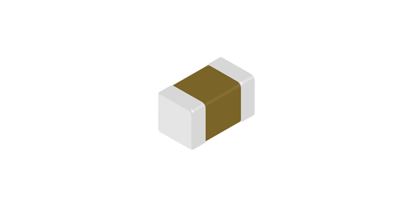
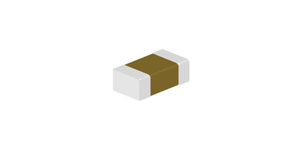
・Offer a diverse products from ultra-compact size (0.4x0.2mm) to large size (3.2x2.5mm)
・May be selected for almost any applications from the combination of temperature characteristics, rated voltage, and packaging.
애플리케이션
- 스마트폰・타블렛PC
- 웨어러블단말기
- 가전기기 (평면 TV, PC, 게임)
- 데이터 센터・AI 서버
- 로봇
- 산업기기
- 기지국
- 통신 모듈
사양
| 시리즈 | General Purpose KGM |
|---|---|
| Size Code (EIA) | 01005 |
| Dimension (L) | 0.4±0.02mm |
| Dimension (W) | 0.2±0.02mm |
| Dimension (T) | 0.2±0.02mm |
| Temperature characteristics | X5R(EIA) |
| 사용온도범위 |
-55℃ ~ 85℃
|
| Max. Capacitance Change in the Temperature | ±15% |
| Capacitance | 0.47μF (474) |
| Capacitance Tolerance | M (±20%) |
| 정격전압 | 6.3Vdc |
| Tanδ | 12.5 |
| 포장 (Reel dia./pitch) | φ180/1mm |
| Quantity per Package | 40000pcs. |
| 제품 질량 | 0.094mg |
| Standard/Optional | Standard specification product |
포장 사양
| 포장 (Reel dia./pitch) | φ180/1mm |
|---|---|
| Quantity per Package | 40000pcs. |
| 제품 질량 | 0.094mg |
엔지니어링 문서
Datasheet
 KGM02AR50J474M-DATA.pdf (606.71KB)
S-parameter (Series)
 KGM02AR50J474M_Spara_Series.s2p (18.44KB)
SPICE Netlist
KGM02AR50J474M_SPICE_Netlist.mod (1.90KB)
Characteristic data
FAQ
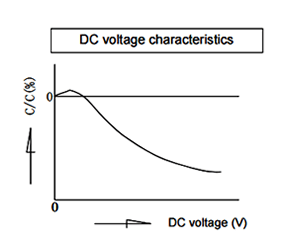
일람The capacitance of a capacitor changes depending on the DC voltage applied. Select a capacitor considering the DC voltage characteristics of the DC circuit in which the capacitor is used. The capacitance of ceramic capacitors might change sharply depending on the applied voltage. (See figure)
Confirm the followings in order to ensure desired capacitance.
- Confirm whether the capacitance change according to the applied voltage is within an allowable range or not.
- Regarding DC voltage characteristics, capacitance decreases as voltage increases, even if the applied voltage is below the rated voltage. Therefore, when a capacitor is used in a circuit with a narrow range of capacitance change allowance like a time constant circuit, it is recommended that the capacitance is within the allowable range under operating voltage.
The soldering conditions (preheating temperature, soldering temperature and their durations) shall be within the limits in the catalogs or product specifications.
When the capacitors are used exceeding the limits given in the catalogs or product specifications, cracks may occur in the capacitors and the reliability may deteriorate, especially the rapid temperature changes and partial heating during soldering may cause cracks.
Generally recommended temperature conditions for reflow soldering is as follows:
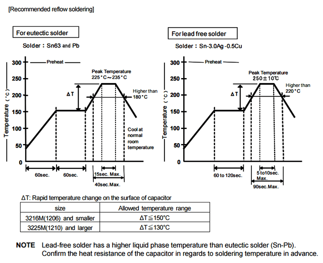
When the capacitors are soldered under long duration or high temperature, the dissolution of electrode (leaching), deterioration of adhesion (shear strength) and capacitance decrease may occur.
Take into consideration tombstone phenomenon (also called "Manhattan phenomenon") for 3216M size or smaller capacitors when the soldering is not proper.
The tombstone phenomenon can be avoided by taking the following measures:
- - reducing land dimensions
- - applying adequate preheating
- - optimizing solder amount
- - ensuring accurate placement
- providing equal heating to both terminations during soldering
Heat stress during rework may possibly be reduced by using a spot heater (also called a "blower") rather than a soldering iron.
General Instruction
When capacitors are reworked using soldering irons beyond the limits stated in the catalogs or product specifications, cracks may occur in the capacitors due to thermal stress and insulation resistance may deteriorate.
When lead-free solder which has a higher melting point (liquid phase temperature of over 200 °C) is used, the risk of cracks is higher due to the larger thermal stress in the capacitor induced if rapid cooling or heating and partial heating occur during reworking.
Do not touch the tip of a soldering iron to the termination electrode of a capacitor.
Reworking using a spot heater may suppress the occurrence of cracks in the capacitor compared to using a soldering iron. A spot heater can heat up a capacitor uniformly with a small heat gradient which leads to lower thermal stress caused by quick heating and cooling or localized heating.
Moreover, where ultra-small capacitors are mounted close together on a printed circuit board, reworking with a spot heater can eliminate the risk of direct contact between the tip of a soldering iron and a capacitor.
Repair Conditions
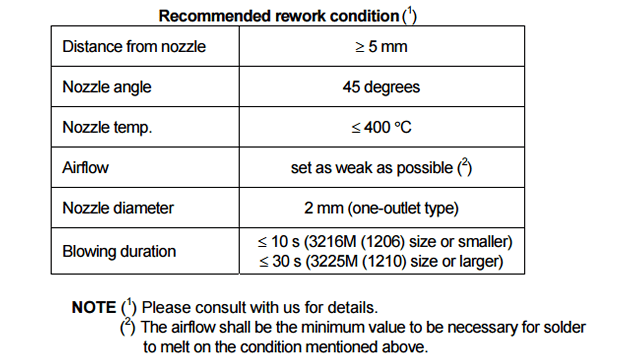
If the blower nozzle of a spot heater is too close to a capacitor, a crack in the capacitor may occur due to heat stress. Below are recommendations for avoiding such an occurrence.
Keep more than 5 mm between a capacitor and a spot heater nozzle.
The blower temperature of the spot heater shall be lower than 400 °C.
The airflow shall be set as weak as possible.
The diameter of the nozzle is recommended to be 2 mm (one-outlet type). The size is standard and common.
Duration of blowing hot air is recommended to be 10 s or less for 3225M size or smaller capacitors, and 30 s or less for 3216M size or larger capacitors, considering surface area of the capacitor and melting temperature of solder.
The angle between the nozzle and the capacitor is recommended to be 45 degrees in order to work easily and to avoid partial area heating.
As is the case when using a soldering iron, preheating reduces thermal stress on capacitors and improves operating efficiency.
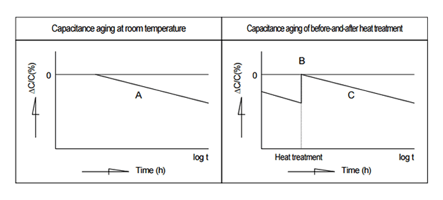
High dielectric constant ceramic material, when left in room temperature without any bias, has tendency to decrease its capacitance almost linearly to logarithmic time. This phenomenon is caused by the dielectric ceramics to transfer to more stable phase, and these are inevitable characteristics. Therefore, it is suggested to consider the capacitance change with time when using capacitors in circuits such as time constant circuit.
Most ceramic dielectrics used for ceramic capacitors have ferroelectric characteristics, and exhibit a curie temperature. Above this temperature, the dielectrics have a highly symmetric cubic crystal structure whereas below the curie temperature, the crystal structure is less symmetrical. Although in single crystals this phase transition is very sharp, in practical ceramics it is often spread over a finite temperature range. In all cases it is linked with a peak in the capacitance/temperature curve.
Under the influence of thermal vibration, the ions in the crystal lattice continue to move to positions of lower potential energy for a long time after the dielectric has cooled down below the curie temperature. This makes capacitance aging, whereby a capacitor's capacitance continually decreases. (Line A in the below graph) However, if the capacitor is heated to a temperature above the curie temperature, de-aging takes place and the capacitance lost through aging is regained. (B point in the below graph) The aging recommences when the capacitor cools down below its curie temperature. (Line C in the below graph)
This is a phenomenon of shifting to a lower energy state by which the ceramic dielectric becomes more stable.Therefore, take capacitance aging into consideration when using a capacitor with Class 2 or Class 3 ceramic dielectrics for a circuit with a narrow range of allowable capacitance change, such as a time constant circuit.
Since the effects of this aging can be reversed, a dielectric's capacitance can be returned to its original value by subjecting it to a higher temperature than its Curie point, e.g. 125°C for BaTiO3. The phenomena can been noticed immediately after soldering or after reworking/repair with a soldering iron.
Related Glossary
일람Mainly CG and CH type capacitors and titanium oxide and zirconate dielectric ceramics are its main materials. With small variation in capacitance due to temperatures, voltages, and ageing, this type is suitable for applications requiring stability; however, rated capacitances are smaller than high dielectric constant type capacitors.
Mainly X5R, X7R, X7S type capacitors, and barium titanate dielectric ceramics are its main material. Compared with the temperature-compensating type, variation in capacitance is larger due to temperatures, voltages, and ageing; however, this type can be smaller in size to gain high capacitance values.
Change of capacitance against the DC voltage.
Index of the ability of how much potential energy can be stored. Unit is "F".


제품번호검색
키워드 검색
카테고리 로 검색
용도로 검색
유통 재고 검색
교세라의 형명을 입력하십시오. 최대 3 가지까지 동시에 검색 할 수 있습니다.