
AC voltage withstanding test
Safety Application Guide for Multilayer Ceramic Chip Capacitors
Design
Electrical factors
AC voltage withstanding test
Confirm test conditions (voltage, time and waveform) of AC voltage withstanding tests for capacitors for electromagnetic interference suppression use in the primary circuits.
- (1) Confirm that the test conditions (voltage, time and waveform) of the AC voltage withstanding tests
at the incoming inspection and/or assembly process are within the specified conditions.
Failure of withstanding voltage may occur when applied voltage or time exceeds the specified conditions. - (2) Confirm a specified voltage wave form for the AC voltage withstanding test.
When the voltage wave form is a sine wave, any peak voltage which is more than √2times of specified effective voltage shall not be applied to the capacitor.
The applied voltage wave form may be distorted by the dielectric material of the capacitor or the withstanding voltage test equipment, so that it may exceed √2times the specified effective voltage.
Distorted wave forms of a sine wave with a voltage of 1000 V rms are shown as follows.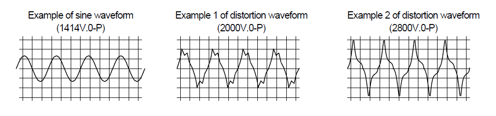
- (3) For the AC voltage withstanding test, apply a specified voltage using a zero crossing start after
the capacitor's terminals are connected securely to the test equipment.
When a spark discharge is generated by a poor connection with test equipment, or by applying voltage with test equipment which does not employ a zero crossing start, abnormal voltage higher than the specified voltage may be generated.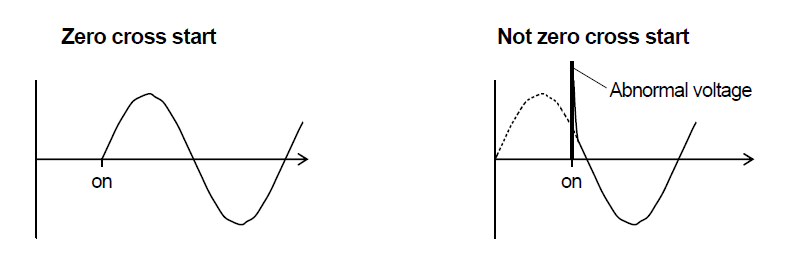
Safety Application Guide for Multilayer Ceramic Chip Capacitors All Lists


제품번호검색
키워드 검색
카테고리 로 검색
용도로 검색
유통 재고 검색
교세라의 형명을 입력하십시오. 최대 3 가지까지 동시에 검색 할 수 있습니다.